


 |
Battery Management ICs High Input Voltage,3A Single-Cell Battery Chargerwith NVDC Power Path Management
Product Details:
| Place of Origin: | Dongguan China |
| Brand Name: | UCHI |
| Certification: | Completed |
| Model Number: | SGM41519 |
Payment & Shipping Terms:
| Minimum Order Quantity: | 1000PCS |
|---|---|
| Price: | Negotiable |
| Packaging Details: | Standard |
| Delivery Time: | 3weeks |
| Payment Terms: | T/T,Western Union |
| Supply Ability: | 5000pcs |
|
Detail Information |
|||
| VAC, VBUS (Converter Not Switching): | -2V To 22V (1) | BTST, PMID (Converter Not Switching): | -0.3V To 22V |
|---|---|---|---|
| SW: | -2V To 16V | SW (Peak For 10ns Duration): | -3V To 16V |
| BTST To SW: | -0.3V To 6V | PSEL, PMID_GD: | -0.3V To 6V |
| Output Sink Current STAT: | 6mA | NINT: | 6mA |
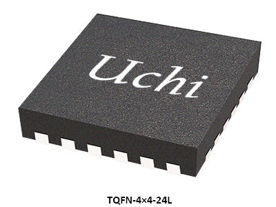
| TQFN-4×4-24L, θJA: | 36℃/W | Junction Temperature: | +150℃ |
| Storage Temperature Range: | -65 To +150℃ | Lead Temperature (Soldering, 10s): | +260℃ |
| HBM: | 5000V | CDM: | 1000V |
| Highlight: | High Input Voltage Battery Management IC,3A Single-Cell Battery Charger IC,NVDC Power Path Management IC |
||
Product Description
The device includes four main power switches: input reverseblocking FET (RBFET, Q1), high-side switching FET for Buckor Boost mode (HSFET, Q2), low-side switching FET for Buckor Boost mode (LSFET, Q3) and battery FET that controls theinterconnection of the system and battery (BATFET, Q4). Thebootstrap diode for the high-side gate driving is alsointegrated. The internal power path has a very low impedancethat reduces the charging time and maximizes the batterydischarge efficiency. Moreover, the input voltage and currentregulations provide maximum charging power delivery to thebattery with various types of input sources.
A wide range of input sources are supported, includingstandard USB hosts, charging ports and USB compliant highvoltage adaptors. The default input current limit isautomatically selected based on the built-in USB interface.This limit is determined by the detection circuit in the system(e.g. USB PHY). The SGM41519 is USB 2.0 and USB 3.0power specifications compliant with input current and voltageregulation.
The SGM41519 is capable of boosting the battery voltage tosupply 5.15V (adjustable 4.85V/5V/5.15V/5.3V) on PMID.The Boost mode is used to charge another battery by thecontrol of PMID_GD. The PMID_GD pin is used to drive anexternal P-MOSFET to disconnect Boost output PMID fromattached accessories.
The system voltage is regulated slightly above the batteryvoltage by the power path management circuit and is keptabove the programmable minimum system voltage (3.5V bydefault). Therefore, system power is maintained even if the battery is completely depleted or removed. Dynamic powermanagement (DPM) feature is also included thatautomatically reduces the charge current if the input currentor voltage limit is reached. If the system load continues toincrease after reduction of charge current down to zero, thepower path management provides the deficit from battery bydischarging battery to the system until the system powerdemand is fulfilled. This is called supplement mode, whichprevents the input source from overloading.
Starting and termination of a charging cycle can beaccomplished without software control. The sensed batteryvoltage is used to decide for starting phase of charging in oneof the three phases of charging cycle: pre-conditioning,constant current or constant voltage. When the chargecurrent falls below a preset limit and the battery voltage isabove recharge threshold, the charger function willautomatically terminate and end the charging cycle. If thevoltage of a charged battery falls below the rechargethreshold, the charger begins another charging cycle.
Several safety features are provided in the SGM41519 suchas over-voltage and over-current protections, batterytemperature monitoring, charging safety timing, thermalshutdown and input UVLO. TS pin is connected to an NTCthermistor for battery temperature monitoring and protectionin both charge and Boost modes according to JEITA profile.This device also features thermal regulation in which thecharge current is reduced, if the junction temperatureexceeds 80℃ or 120℃ (selectable).
Charging status is reported by the STAT output andfault/status bits. A negative pulse is sent to the nINT outputpin as soon as a fault occurs to notify the host. BATFET resetcontrol is provided by nQON pin to exit ship mode or for a fullsystem reset.The SGM41519 is available in a Green TQFN-4×4-24Lpackage.
● High Efficiency, 1.5MHz, Synchronous Buck Charger
93.8% Charge Efficiency at 1.02A from 5V Input
89.8% Charge Efficiency at 2A from 9V Input
Optimized for 9V/12V Input Selectable PFM Mode for Light Load Efficiency
● Boost Mode Support
Output Voltage Range from 4.85V to 5.3V
Boost Efficiency of 93.5% at 0.5A and 92.2% at 1A
Output Short Circuit Protection
Selectable PFM Mode for Light Load Operations
PMID_GD Pin Control External P-MOSFET forProtection against Fault Conditions
● Automatic Switch between Charge and Boost Mode
● Single Input for USB or High Voltage Adaptors
3.9V to 13.5V Operating Input Voltage Range
22V Absolute Maximum Input Voltage Rating
Programmable Input Current Limit and DynamicPower Management (IINDPM, 100mA to 3.2A with100mA Resolution) to Support USB 2.0 and USB 3.0 Standards and High Voltage Adaptors
Maximum Power Tracking by Programmable InputVoltage Limit (VINDPM) with Selectable Offset
VINDPM Tracking of Battery Voltage
● High Battery Discharge Efficiency with 26mΩ Switch
● Narrow Voltage DC (NVDC) Power Path Management
Instant-On with No or Highly Depleted Battery
Ideal Diode Operation in Battery Supplement Mode
● Ship Mode, Wake-Up and Full System Reset Capabilityby Battery FET Control
● Flexible Autonomous and I2C Operation Modes forOptimal System Performance
● Fully Integrated Switches, Current Sense andCompensation
● 2.5μA Ship Mode Low Battery Leakage Current
● High Accuracy
±0.5% Charge Voltage Regulation (8mV/Step)
±5% Charge Current Regulation at 1.38A
±10% Input Current Regulation at 0.9A
● Safety
Battery Temperature Sensing (Charge/Boost Modes)
Thermal Regulation and Thermal Shutdown
Input Under-Voltage Lockout (UVLO)
Input Over-Voltage (ACOV) Protection
Portable Internet Devices and Accessory
Pin Configurations
Pin Description
Product Selection Guid
| Part Number |
Number of
Series Cells
|
Input Over-Voltage
Protection Threshold
(V)
|
Charge
Voltage
(V)
|
VIN
Min
(V)
|
VIN
Max
(V)
|
Programmable
Current
(mA)
|
Shutdown
Current
From VIN
(μA)
|
Status
Indication
|
Foldback
Current
From Battery
(μA)
|
Packag
|
Features |
|---|---|---|---|---|---|---|---|---|---|---|---|
|
SGM41509
|
1 |
Adj (Default 5.65)
|
3.84 ~ 4.608 |
3.9
|
5.5 |
0 ~ 5056
|
50 | Yes | 25 |
TQFN-4×4-24L
|
I2C Controlled 5A Single-Cell Battery Charger with Power Path Management
|
|
SGM41510
|
1 |
Adj (Default 15.1)
|
3.84 ~ 4.608 |
3.9
|
14
|
0 ~ 5120
|
50 |
Yes
|
20 |
TQFN-4×4-24L
|
I2C Controlled 5A Single-Cell Battery Charger with Power Path Management
|
|
SGM41511
|
1 | 6.5,10.5,14 | 3.856 ~ 4.624 |
3.9
|
13.5
|
0 ~ 3000
|
45 |
Yes
|
20 |
TQFN-4×4-24L
|
I2C Controlled 5A Single-Cell Battery Charger with Power Path Management |
|
SGM41512
|
1 |
6.5,10.5,14
|
3.848 ~ 4.616
|
3.9
|
13.5
|
0 ~ 3000
|
45 |
Yes
|
20 |
TQFN-4×4-24L
|
I2C Controlled 5A Single-Cell Battery Charger with Power Path Management |
|
SGM41512A
|
1 |
6.5,10.5,14
|
3.848 ~ 4.616
|
3.9
|
13.5
|
0 ~ 3000
|
45 |
Yes
|
20 |
TQFN-4×4-24L
|
I2C Controlled 5A Single-Cell Battery Charger with Power Path Management |
|
SGM41513/A/D
|
1 |
6.5,10.5,14
|
3.856 ~ 4.624
|
3.9
|
13.5
|
0 ~ 3000
|
38 |
Yes
|
8.5 |
TQFN-4×4-24L
|
3A Single-Cell Battery Charger with Power Path Management
|
|
SGM41515/A/D
|
1 |
6.5,10.5,14
|
3.856 ~ 4.624 |
3.9
|
13.5
|
0 ~ 3000
|
38 |
Yes
|
8.5 |
TQFN-4×4-24L
|
3A Single-Cell Battery Charger with Power Path Management
|
|
SGM41515E
|
11 |
6.5,10.5,14
|
3.856 ~ 4.624
|
3.9
|
13.5
|
0 ~ 3000
|
38 |
Yes
|
8.5 |
TQFN-4×4-24L
|
3A Single-Cell Battery Charger with Power Path Management
|
|
SGM41516D
|
1 |
6.5,10.5,14
|
3.856 ~ 4.624 |
3.9
|
13.5
|
0 ~ 3780
|
55 |
Yes
|
15 |
WLCSP-2.0×2.4-30B
|
3.78A Single-Cell Battery Charger with Power Path Management
|
|
SGM41518
|
1 |
6.5,10.5,14
|
3.856 ~ 4.624 |
3.9
|
13.5
|
0 ~ 1260
|
40 |
Yes
|
15 |
WLCSP-2.0×2.4-30B
|
1.26A Single-Cell Battery Charger with Power Path Management
|
|
SGM41519
|
1 |
6.5,10.5,14
|
3.856 ~ 4.624 |
3.9
|
13.5
|
0 ~ 3000
|
38 |
Yes
|
8.5 |
TQFN-4×4-24L
|
3A Single-Cell Battery Charger with Power Path Management
|
|
SGM41519A
|
1 |
6.5,10.5,14
|
3.856 ~ 4.624 |
3.9
|
13.5
|
0 ~ 3000
|
38 |
Yes
|
8.5 |
TQFN-4×4-24L
|
3A Single-Cell Battery Charger with Power Path Management
|
|
SGM41521B
|
1 |
6.5,10.5,14
|
3.856 ~ 4.624 |
3.9
|
13.5 |
0 ~ 3000
|
45 |
Yes
|
20 |
TQFN-4×4-24L
|
I2C Controlled 5A Single-Cell Battery Charger with Power Path Management |
|
SGM41522
|
1 |
13.5
|
4.1 ~ 4.45
|
4.2 | 13.2 |
0 ~ 2500
|
Yes
|
4.5 |
TDFN-2×3-8BL
|
Compact Switch, 2.5A Standalone Single-Cell Battery Charger with Safe and Reliable Charging
|
|
|
SGM41523
|
1 |
13.5
|
4.1 ~ 4.45
|
4.2 | 13.2 |
0 ~ 2500
|
Yes
|
4.5 |
TDFN-3×3-12L
|
Compact Switch, 2.5A Standalone Single-Cell Battery Charger with Safe and Reliable Charging
|
|
|
SGM41524
|
1 |
5.67
|
4.2 ~ 4.5 |
3.5
|
5.5 |
300 ~ 2300
|
15 |
Yes
|
<1.4
|
TDFN-2×3-8BL
|
Compact Switch Li+/Poly Battery Charger Safe and Reliable Charging
|
|
SGM41524C
|
1 | 5.67 | 4.2 ~ 4.5 | 3.5 | 5.5 |
300 ~ 2300
|
15 |
Yes
|
<1.4
|
TDFN-2×3-8BL
|
Compact Switch Li+/Poly Battery Charger Safe and Reliable Charging
|
|
SGM41544/D
|
1 | 6.5,10.5,14.3 | 3.856 ~ 4.624 | 3.9 |
14
|
0 ~ 5000
|
50 |
Yes
|
13 |
TQFN-4×4-24L
|
5A Single-Cell Battery Charger with Power Path Management
|
|
SGM41538/B
|
1 to 4
|
25.7
|
1.024 ~ 19.2
|
4.5
|
24
|
0 ~ 8128
|
50 |
Yes
|
TQFN-4×4-28BL
|
SMBus Hybrid Power Boost Mode Battery Charge Controller
|
|
|
SGM41575
|
1 to 4
|
7,12,22,26
|
3 ~ 18.8
|
3.6
|
24
|
0 ~ 5000
|
287
|
Yes
|
22
|
WLCSP-2.97×3.37-56B
|
I 2C Controlled, 1-4 Cells, 5A Fully Integrated Buck-Boost Battery Charger with Narrow VDC Power Path Management
|
This solution demonstrates the application of integrated circuits in smart phones and tablets. For assistance selecting the right product, please contact our technical support team.