


 |
Water‑Circulation Temperature‑Control Module for Intelligent Liquid‑Cooled Mattress
Product Details:
| Place of Origin: | Dongguan,Guangdong,China |
| Brand Name: | UCHI |
| Certification: | UL.VDE,SGS,REACH,CQC,CSA.ISO.ROHS,CUL |
Payment & Shipping Terms:
| Minimum Order Quantity: | 1000PCS |
|---|---|
| Price: | Negotiable |
| Packaging Details: | Bulk |
| Delivery Time: | 5-7 days |
| Payment Terms: | T/T,Paypal,Western Union, |
| Supply Ability: | 5000,000,000PCS Per Month |
|
Detail Information |
|||
| Mountingoptions: | Screw Holes Or Adhesive Pads | Flowrate: | Up To 10 L/min |
|---|---|---|---|
| Product Technology: | CNC Machine + Surface Finish | Grade: | Copper |
| Body Material: | Aluminum | Coolant Type: | Ethylene Glycol Solution Or Silicone Oil |
| Thermal Dissipation Power: | 2000W | Altitude: | ≤2000m |
| Process: | Epoxy Bonding | Conducting Power: | 500 W |
| Operatingtemperaturerange: | -40°C To 120°C | Ambient Temperature: | -25°C To 65°C |
| Base Material: | Aluminum Or Copper | ||
| Highlight: | Water-Circulation Temperature-Control Module,Intelligent Liquid-Cooled Mattress Module,Liquid Cooling Plate with Temperature Control |
||
Product Description
Full Assembly Process of Temperature Control Host for Liquid-Cooled Mattress (All Components Corresponding to the Three Diagrams)
I. Complete Bill of Materials (Components Matched with the Three Diagrams)
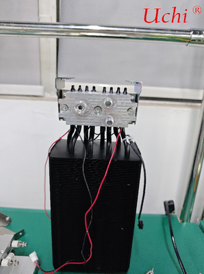
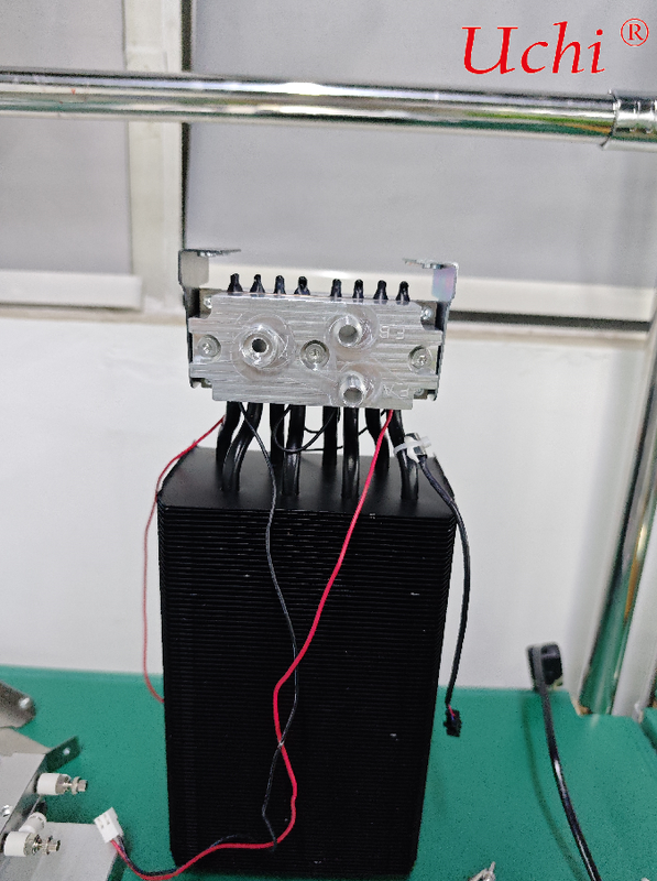
Refrigeration Core Module (Diagram 1): Dual-circuit aluminum water cooling plates, 8 heat-conducting heat pipes, multiple TEC thermoelectric cooling chips, red and black power supply wires for TEC chips
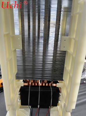
Heat Dissipation Assembly (Diagram 3): Nylon insulated air duct bracket, high-density aluminum fin radiator, copper heat equalizing pipes, black heat-conducting base for TEC chips
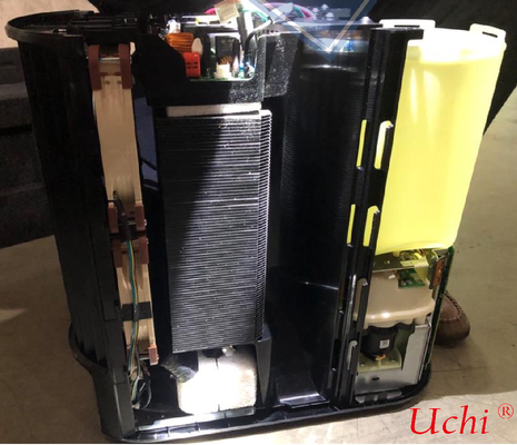
Main Housing, Water Circuit and Electronic Control Components (Disassembled Main Unit Diagram 2): Plastic main unit shell, water storage tank, silent circulating water pump, main control PCB circuit board, shock-absorbing sponge, wire harness clips, DC cooling fan, water level sensor, temperature probe, external operation panel
II. Step 1: Laminated Assembly of Refrigeration Core and Heat Dissipation Assembly (Hot End Assembly of Core Components)
Clean the hot end surfaces of TEC cooling chips and the flat surface of the black copper base, then evenly apply a thin layer of thermal grease to fill gaps and reduce thermal resistance.
Press the hot ends of multiple TEC cooling chips tightly against the black base and temporarily secure them with cable ties; arrange the cold ends of TEC chips upward to align with the dual-circuit aluminum water cooling plates above.
Insert one end of each copper heat pipe into the pre-reserved pipe grooves of the black base, and feed the other end through the upper high-density aluminum fin radiator. Ensure each heat pipe forms a tight interference fit with the fins without loose gaps.
Fit the beige nylon insulated air duct bracket, align the mounting holes on both sides of the radiator and fasten them with screws to form a closed vertical air duct, ensuring all airflow from the fan passes through the aluminum fins.
Connect the red and black power supply wires of TEC chips, route the wire harness through the pre-set wire grooves of the bracket and fix with clips to prevent short circuits caused by contact with the metal radiator.
III. Step 2: Assembly of Cold-End Water Circuit Water Cooling Plates
Apply another thin layer of thermal grease on the cold end surfaces of TEC chips, align the dual-circuit FA/EB aluminum water cooling plates shown in Diagram 1, and vertically press them to closely fit all cold ends of TEC chips.
Tighten the fixing screws on both sides of the water cooling plates with uniform force to avoid cracking TEC chips under stress; check that the three quick-connect water ports are unobstructed and reserve space for external mattress pipelines.
Install thermal gaskets at contact points between the upper ends of the 8 heat-conducting heat pipes and the back of the water cooling plates to help balance cold-end temperature and eliminate local temperature differences.
IV. Step 3: Pre-Assembly of Water Circuit System (Water Tank + Water Pump)
Take out the plastic main unit shell, install the yellow water storage tank into the right cabin and fasten the limit clips to prevent shaking and water leakage.
Connect the bottom of the water storage tank to the silent DC circulating water pump, and compress the sealing ring to stop water seepage; connect the water inlet and outlet of the pump to the FA and EB circulating ports of the water cooling plates via silicone hoses.
Connect a water flow sensor and water temperature probe in series to the water circuit, arrange all pipelines into the side wire grooves and reserve a water replenishing overflow port; fasten all joints with hose clamps to prevent water seepage during circulation.
Paste white shock-absorbing sponge at the bottom of the water pump and radiator to isolate vibration and reduce operating noise of the whole unit at night.
V. Step 4: Wiring and Installation of Electronic Control System
Install the main control PCB circuit board into the top cabin of the main unit and fix insulating support posts to avoid contact between the circuit board and the metal radiator.
Connect wire harnesses by category:
Power wires: Connect TEC red and black power wires, water pump power cords and cooling fan power cords to the power output terminals of the main board.
Sensor signal wires: Connect water temperature probes, mattress zoning temperature sensors and low-water-level sensors to the signal acquisition terminals of the main board.
Panel communication wires: Plug the flat cable of the external operation panel into the communication interface of the main board.
Fix all wire harnesses in layers in the left wire groove with brown plastic clips and arrange neatly to prevent pipelines and fans from scraping wires; coil and fix redundant wires to eliminate resonance noise.
VI. Step 5: Main Unit Casing Closing and Air Duct Assembly
Push the fully assembled refrigeration and heat dissipation module into the middle cabin of the main unit as a whole, and fasten it to the base with screws.
Mount the DC cooling fan at the air duct position on the front of the radiator, with the fan blowing air toward aluminum fins to form forced convection heat dissipation.
Align the clips on the upper and lower plastic shells of the main unit, fasten the whole unit and lock the shell with screws; reserve outlets for external water pipes of the water cooling plates and power cords.
Inspect all movable parts: the fan rotates without friction, the water pump runs smoothly without jamming, the water tank can be pulled out normally for water replenishment, and water circuit joints are free of extrusion and bending.
VII. Step 6: Water and Power Test of Complete Unit (Mandatory Factory Inspection)
Water Circuit Test
Fill the water tank with distilled water, start the water pump for 10-minute circulation, and check all joints and water cooling plates for seepage or dripping water.
Verify the water flow sensor can detect water flow normally; the main board shall trigger low-water protection to shut down the unit when there is no water.
Temperature Control Performance Test
Power on the operation panel, set cooling mode at 18°C and heating mode at 45°C respectively to test independent temperature control of the dual-circuit water channels.
Run continuously for 2 hours, check that the radiator has no overheating, the fan speed remains stable, and TEC chips have no high-temperature frequency reduction.
The measured night noise shall not exceed 35dB, with no obvious vibration from water flow or abnormal fan noise.
Protection Function Test
Manually block the air duct of the radiator; the main board shall automatically cut off power supply to TEC chips via over-temperature protection.
Drain all water from the water tank; low-water protection will shut down the whole unit and trigger a low-water alarm prompt on the panel.
VIII. Key Assembly Pitfall Avoidance Tips
⚠️ Do not apply an overly thick layer of thermal grease; only a thin coating is needed. Excessively thick grease will greatly increase thermal resistance and reduce refrigeration efficiency.
Never bend or flatten copper heat pipes; blocked internal working medium backflow will directly disable heat dissipation.
The nylon insulated bracket must not be omitted or removed, otherwise contact between the metal radiator and power supply lines will cause short circuits and burn out the circuit board.
Only distilled water is applicable to the water circuit; tap water is prohibited during assembly and testing to prevent premature pipeline scaling and blockage.
