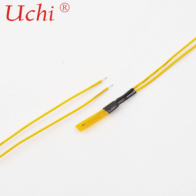
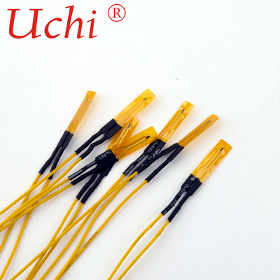
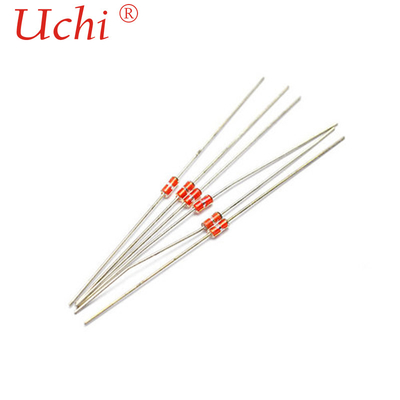
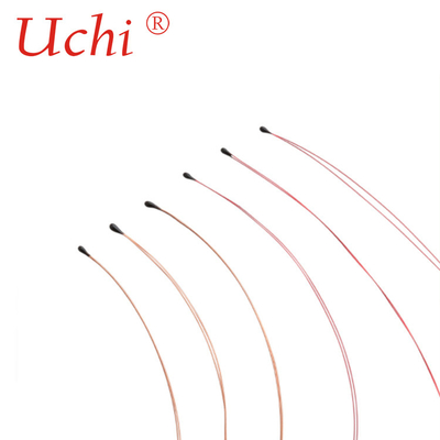
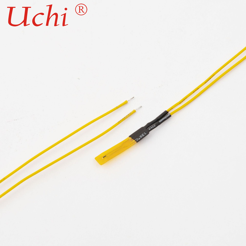
Home Appliances Ntc Thermistor Temperature Sensor For Computers And Printers
Product Details:
| Place of Origin: | Dongguan,Guangdong,China |
| Brand Name: | UCHI |
| Certification: | ROHS,ISO |
| Model Number: | IT |
Payment & Shipping Terms:
| Minimum Order Quantity: | 1000PCS |
|---|---|
| Price: | Negetiable |
| Packaging Details: | Bulk |
| Delivery Time: | 7 working days |
| Payment Terms: | T/T Paypal |
| Supply Ability: | 50000000PCS per month |
|
Detail Information |
|||
| Operating Temperature Range: | -30 ~ 110 °C | Maximum Power Rating: | 3.5 MW : -30 ~ 110 (in Air) (at 25°C) |
|---|---|---|---|
| Dissipation Factor: | Approx. 0.7 MW/°C(in Air) | Thermal Time Constant: | Approx. 5.0 S : 3.5 MW : -30 ~ 110 (in Air) |
| Rated Zero-power Resistance: | 10 KΩ ± 1 % (at 25°C) | Brand: | UCHI |
| Highlight: | Printers Ntc Thermistor Temperature Sensor,Computers Ntc Thermistor Temperature Sensor,Home Appliances NTC Thermistor |
||
Product Description
Ntc Thermistor Temperature Sensor For Computers And Printers Home Appliances
Scope
This specification defines ratings, dimension, insulation, climatic test and mechanical characteristics for MJT type thermistor
Climatic test
Dry Heat
After the test samples are exposed in air at 90±1°C for 1,000 hours, the change ratio of the rated zero-power resistance shall be within ±1% of the initial value.
Damp heat
After the test samples are exposed in the humidity of 95% at 40±2°C for 1,000 hours, the change ratio of the rated zero-power resistance shall be within ±1% of the initial value.
Cold
After the test samples are exposed in air at –30±1°C for 1,000 hours, the change ratio of the rated zero-power resistance shall be within ±1% of the initial value.
Loading
After DC 1mA current is applied to the test samples in the temperature of 40±2°C and the humidity of 95% for 1,000 hours, the change ratio of the rated zero-power resistance shall be within ±1% of the initial value.
![]()
Mechanical characteristics
1. Resistance to soldering heat
The terminals shall be dipped in to a soldering bath having a temperature of 260±5°C to a point 2.0 mm from the body and then be held there for 5 ±1s, the change ratio of the rated zero-power resistance shall be within ±1% of the initial value.
2. Solderability
After dipping the terminal to a depth in a soldering bath of 235±5°C for 2
±0.5s .Approximately 90% of terminals should be covered with solder
uniformly.
3. Free fall
After three times fall to a maple board from 0.75 m high, there shall be no visible damage and the change ratio of the rated zero-power resistance shall be within ±1% of the initial value.
4. Robustness of terminations
After 1N loading weight for 10 ± 1s was applied to the wire terminations, there shall be no visible damage and the change ratio of the rated zero-power resistance shall be within ±1% of the initial
value.
![]()


